by Frank Ress
The Inspiration
I took on the role of president for our chapter in mid-2023. One of the things I noticed reading other chapter newsletters was that some held annual contests for their members. They award points for builds that conform to monthly meeting themes, then recognize the member who accumulates the greatest number of points at the end of each year.
I thought an annual contest might be fun for our club, too, and hoped it would encourage more model building. But there’s more to participating than just building models, so I wanted to recognize additional ways of contributing to the group – incorporating things like meeting attendance, writing kit reviews, delivering some kind of program at a meeting, joining the national organization, etc.
We created an initial point system for various activities and held our first ‘Member Contribution Award’ contest in 2024. We hadn’t decided what the ‘prize’ would be, but thought perhaps cash and a certificate? TBD.
A golf league that I once belonged to had a travelling trophy (a la the Stanley Cup). Each champion’s name got added to the base, and the winner got to hold the trophy for a year. I thought that might be a better prize than (or in addition to) cash.
I considered approaching a trophy shop to make one for us, but when I considered a figure to crown the trophy, I wanted something that would appropriately recognize the club. I thought that might be a tall (likely expensive) order from a shop. I thought, “I’m a model builder – I should be able to make the figure myself (and save the club a little money).”
Once I decided to make the figure, the rest seemed straightforward. I’m a woodworker, too. I had pieces of nice wood on hand that I thought I could use. I had some finish plywood scraps I’d scavenged from someone’s cabinet installation to make a basic box. I had pieces of hardwood board I could use to make the top and bottom of the base. (After making the original parts for the base, I didn’t like the way the grain of one piece matched the rest, so I did end up buying another board that looked better.)
The Base
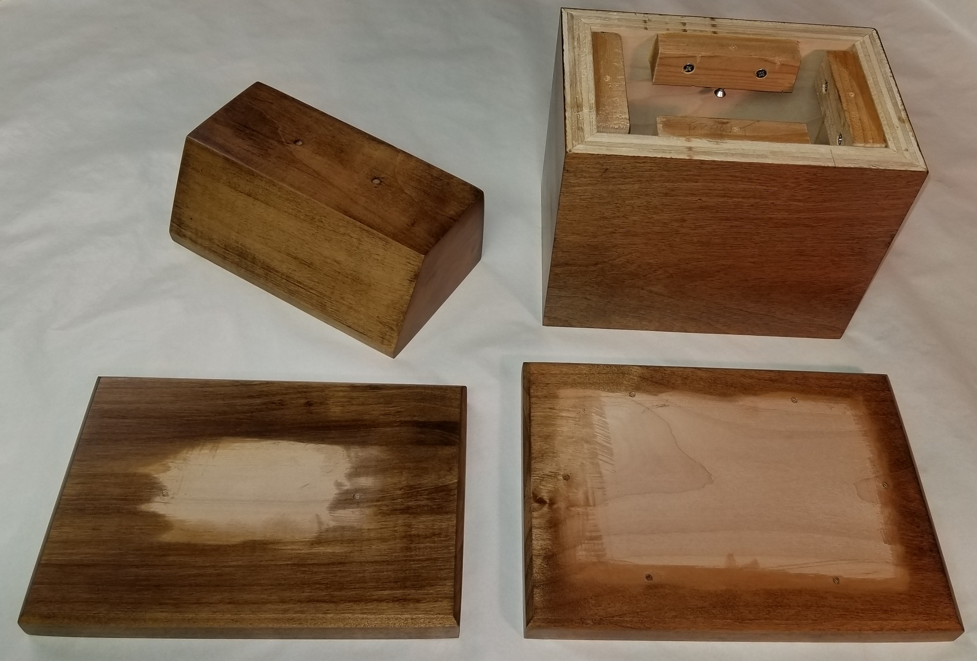
The base would consist of a bottom plate, a box that would be the display area for winner nameplates, and a cap. The logo figure would sit on top of the cap. I also realized that I’d need a place to attach a title plate for the trophy. The logical place for that was above the cap plate and below the figure, so I found another block of maple that I had in my stash. I cut a beveled face to display the title plate at a pleasing slope.
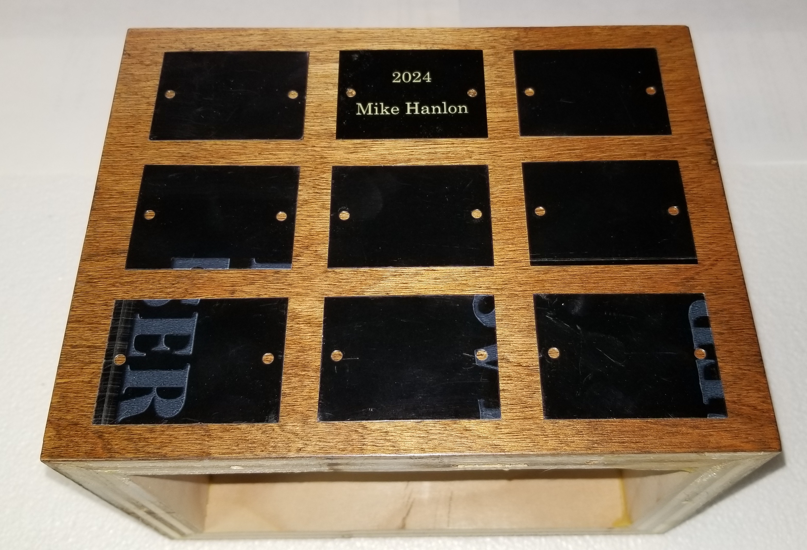
Fig. 1 shows the finished components that make up the base of the trophy. Fig. 2 shows how winner nameplates would be distributed on the front of the trophy. The sides could accommodate 6 nameplates each, so if all 4 sides are used the trophy could recognize 30 years of winners without modification. If this program continues for longer than that – let’s hope so, but I won’t be around to see it – a 2nd tier could be added beneath the existing base. I chose to use screws to attach the winner plates, rather than adhesive, to allow plates to be relocated. That way, the most recent winners can be kept on the front face.
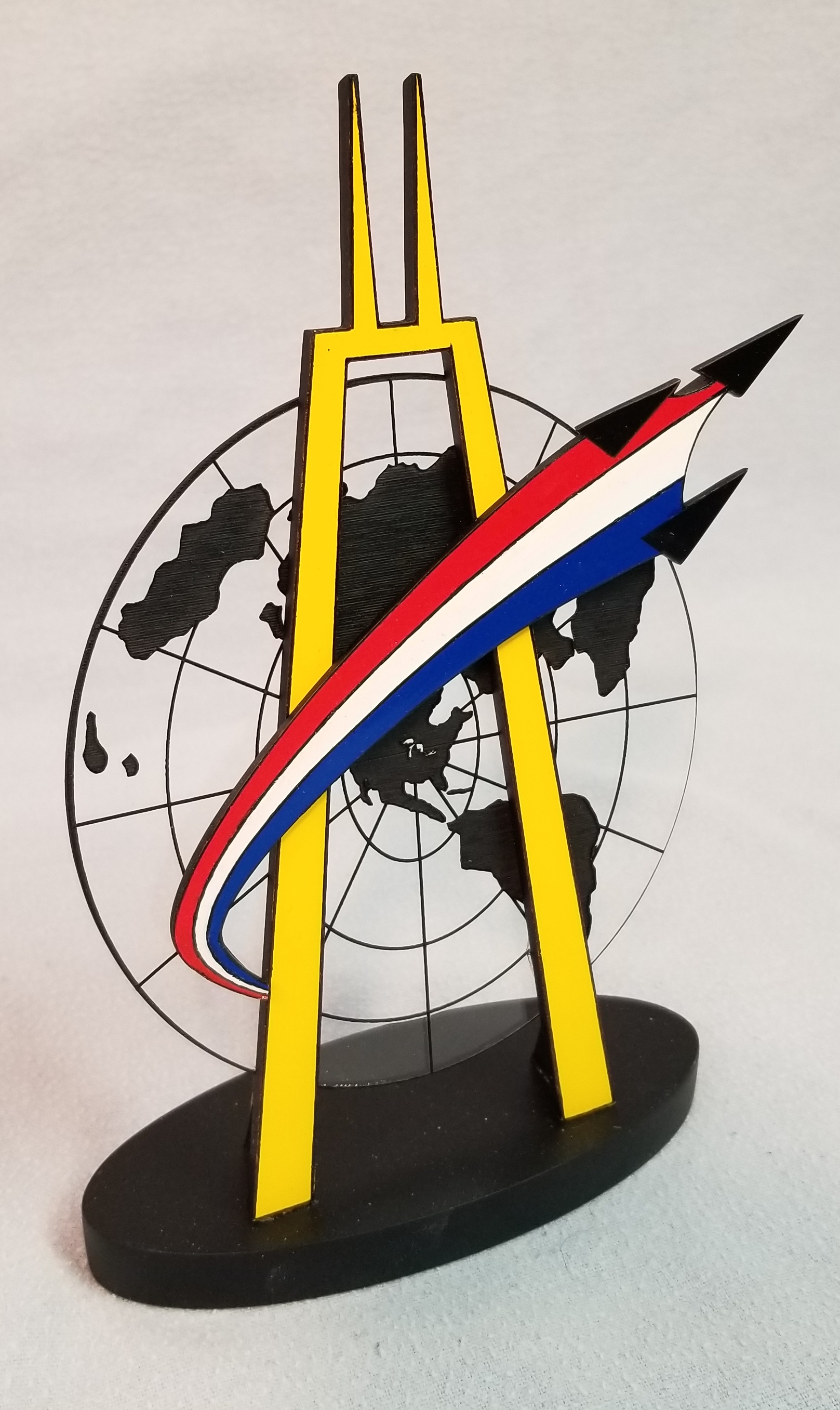
The Figure
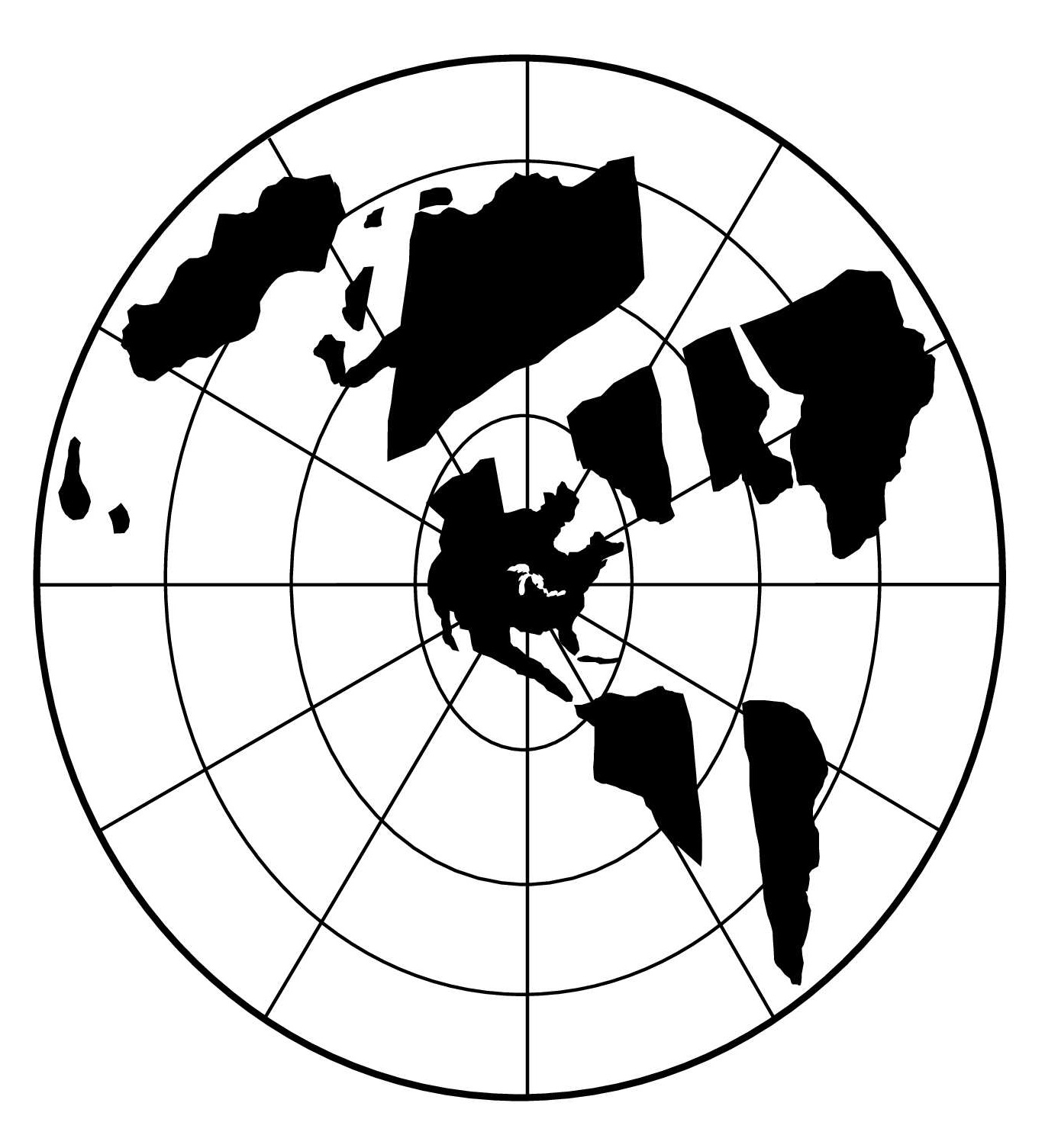
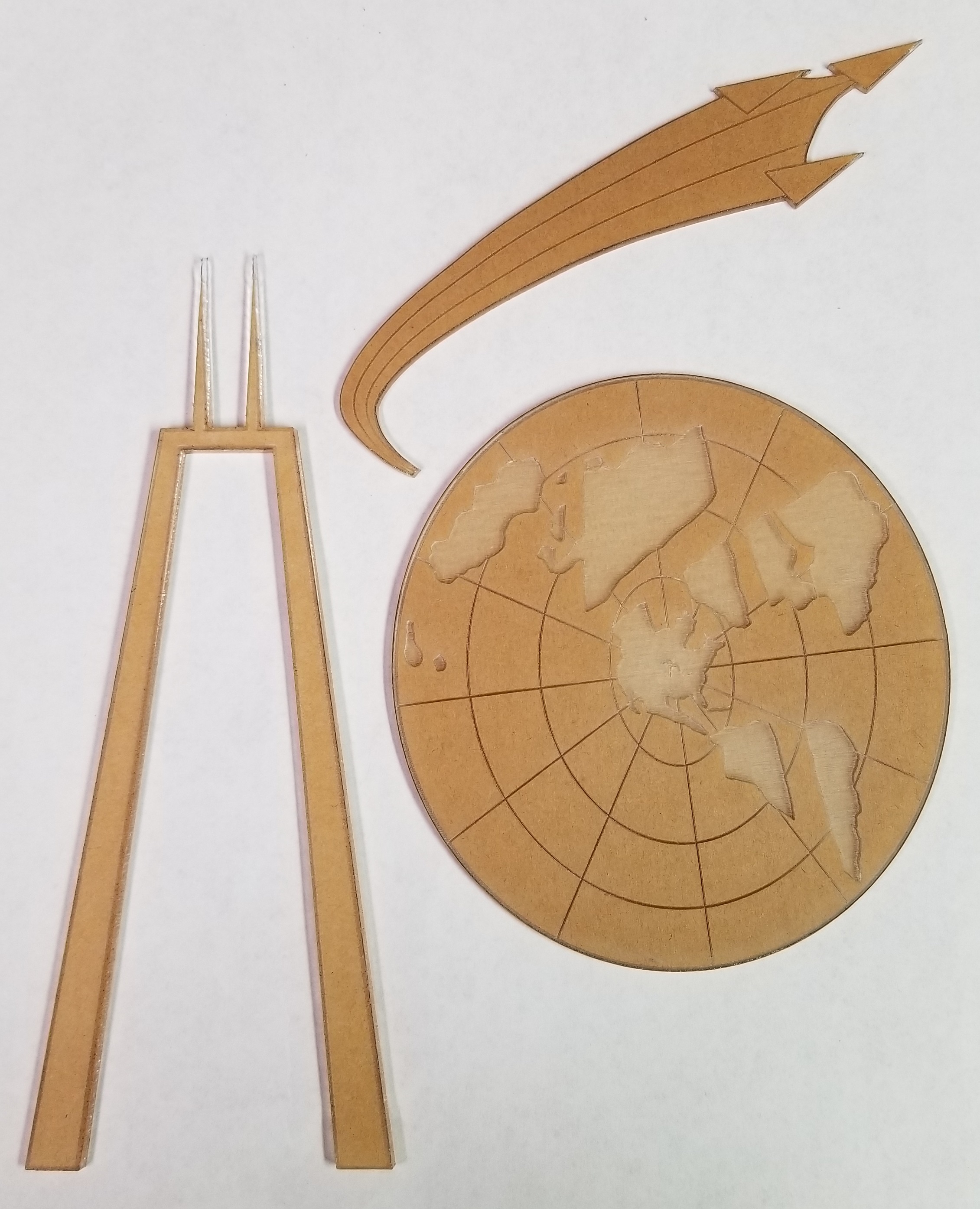
The design for the figure was taken from the club logo (Fig. 3). The logo itself was designed by one of the original club members over 50 years ago, when McK was first chartered. I wanted to incorporate the 3 main elements – the ‘world projection’ that was taken from the IPMS-USA logo, a stylized John Hancock building to represent our Chicago home, and the ‘swoosh’ of 3 jets that represent a missing man formation to represent our namesake, Capt. McKinstry. I already had a fair selection of sheet plastic on hand that I could use for materials.
I printed a copy of the logo on my laser printer, scaled to the size I wanted, then cut out the individual elements to use as paper templates. I began cutting the swoosh and Hancock from 1/16th and 1/8th sheet (respectively) on my bandsaw. Looking at the amount of clean up, filing, and sanding I’d need to do to complete these pieces, I decided to try using a laser cutter instead.
Our library built a ‘Makerplace’ a couple of years ago, with several 3D printers, a couple of laser cutters (a Dremel LC40 and an Epilog Model 17000), and other similar tools. I had already taken a 2-hr intro course on using the laser cutters and figured this might be an opportunity to try it out. I’d started using freeware software (Inkscape) to make designs after the class. I began using that in earnest to design the parts for the trophy.
One advantage of the laser cutter was that I could engrave, as well as cut. Painting the landmasses and lines on a clear plastic sheet seemed a daunting task. Using the laser cutter to engrave those features seemed an easier approach. It also had the advantage that I could engrave through the protective paper on the material. Instant mask! Just engrave, spray, and peel! In the end, that worked well – but the devil, as they say, is in the details!
I used Inkscape to make a 2D rendering of each element of the logo. I imported the image file of the logo into Inkscape, then designed right over it to translate it into lines, ellipses, curves, and irregular shapes (the landmasses). Fig. 4 illustrates how the image was used as a background as each element was modeled in Inkscape. Note how the stylized latitude and longitude lines of the original image are represented by overlayed lines and ellipses. Fig. 5 illustrates the same view, after the landmasses were added to the design and the background image was hidden.
The laser cutter will accept PDF files as input, so once a design was ready, I saved a copy as a PDF file of that element for printing. For convenience, I put all the elements in a single Inkscape design file, and put the components of each element (lines, shapes, etc.) on a separate layer. That allowed me to see the elements stacked atop one another in their correct size and position relative to one another. When I wanted to create the PDF for a single element (to cut or etch), I’d turn off all the other layers before saving the PDF file for that element.
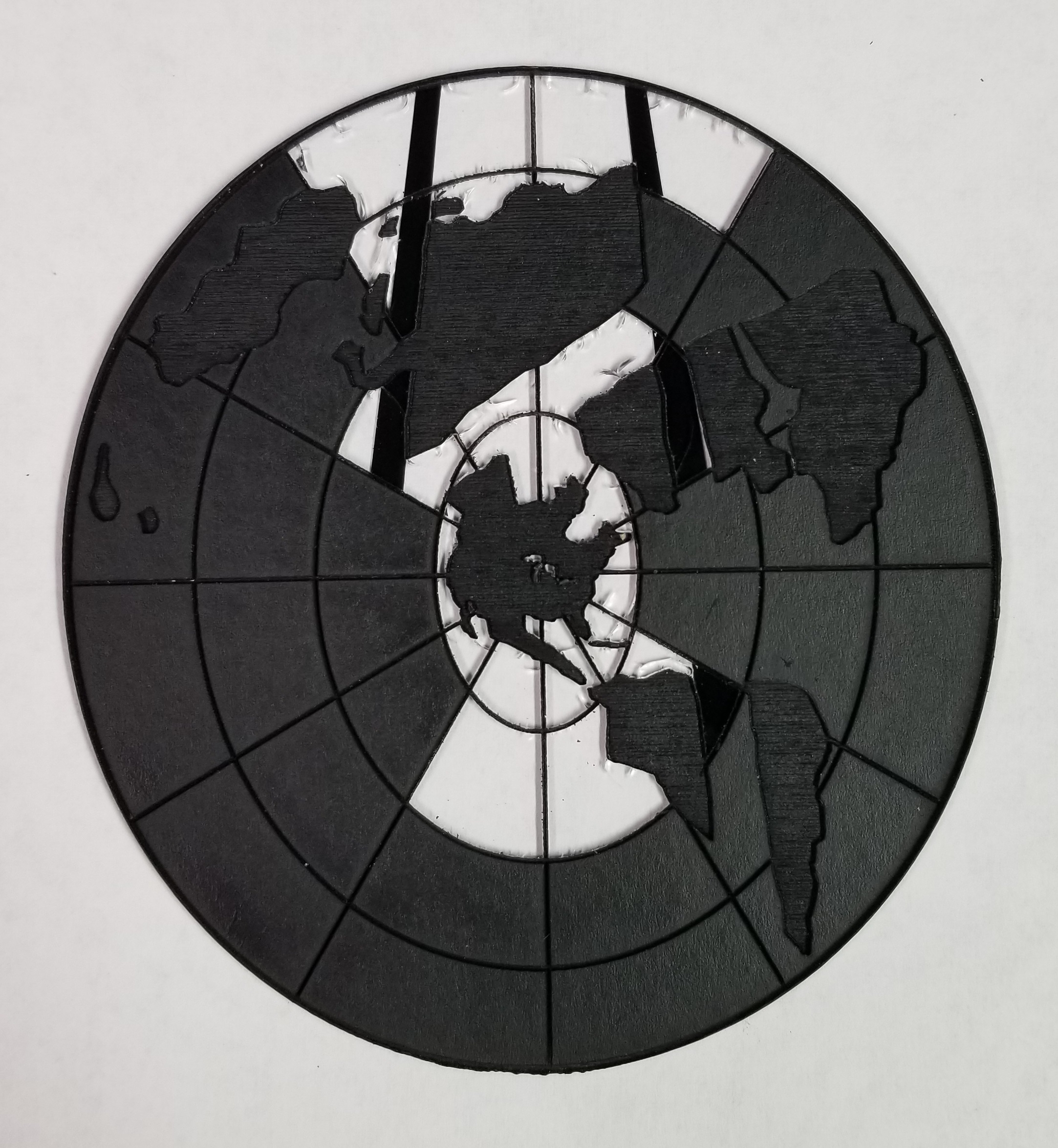
Fig. 6 shows all three elements after they were cut and etched, Fig. 7 shows the painted map with some of the masking removed. I used the Dremel machine for most of my work, since it had more basic capabilities than the Epilog, but was sufficient for my purposes. Demand for the Epilog made getting time on it more difficult.
I used a Tamiya rattle can for the flat black and I airbrushed Testors enamels for the colored areas. As I spraypainted the Hancock and ‘swoosh’ pieces, I noticed numerous fine cracks appearing in the acrylic. If you look closely at Fig. 7 you can see some of these in the exposed clear areas. I decided to go back and finish the 2 pieces that I’d originally started to make by hand, since that material wasn’t as brittle as what was recommended by the library for use with the laser cutter. It took longer, and I wasn’t able to engrave these parts, but I was confident that they’d be sturdy.
The map was a different story. Not using the laser to etch it would be a major headache. I tried one more time (the part in Fig. 7), but the cracks were just too extensive to ignore.
It finally occurred to me that I might be able to find better material. I ordered acrylic sheet from a couple other online vendors and the results were much better. I now had acceptable results for all 3 parts of the figure.
The Figure Base
I needed a base for the figure, since attaching the ‘legs’ of the Hancock directly to the wood pedestal wasn’t a good approach. I wanted to cement the figure to the base, then screw the base to the wood pedestal from below.
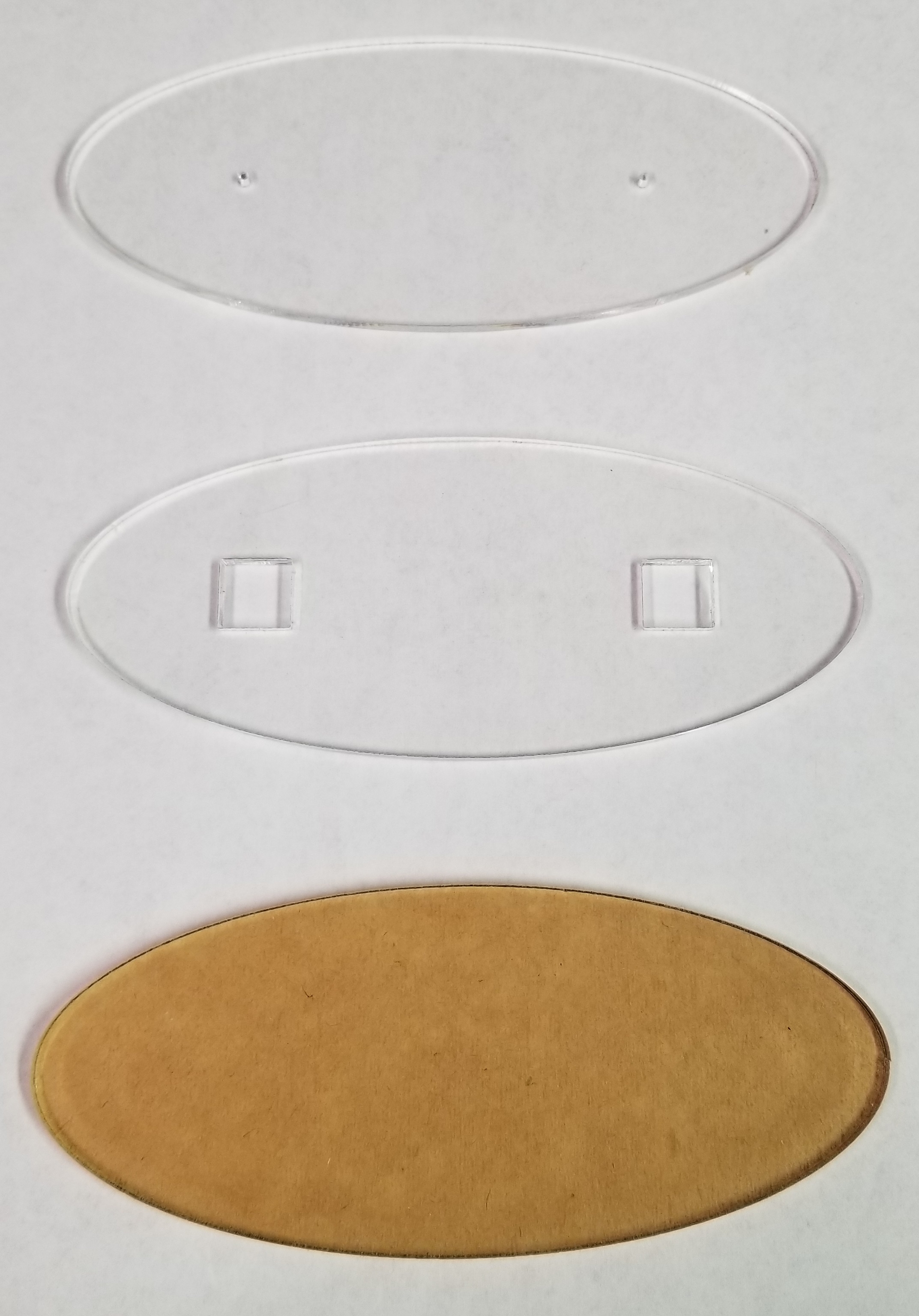
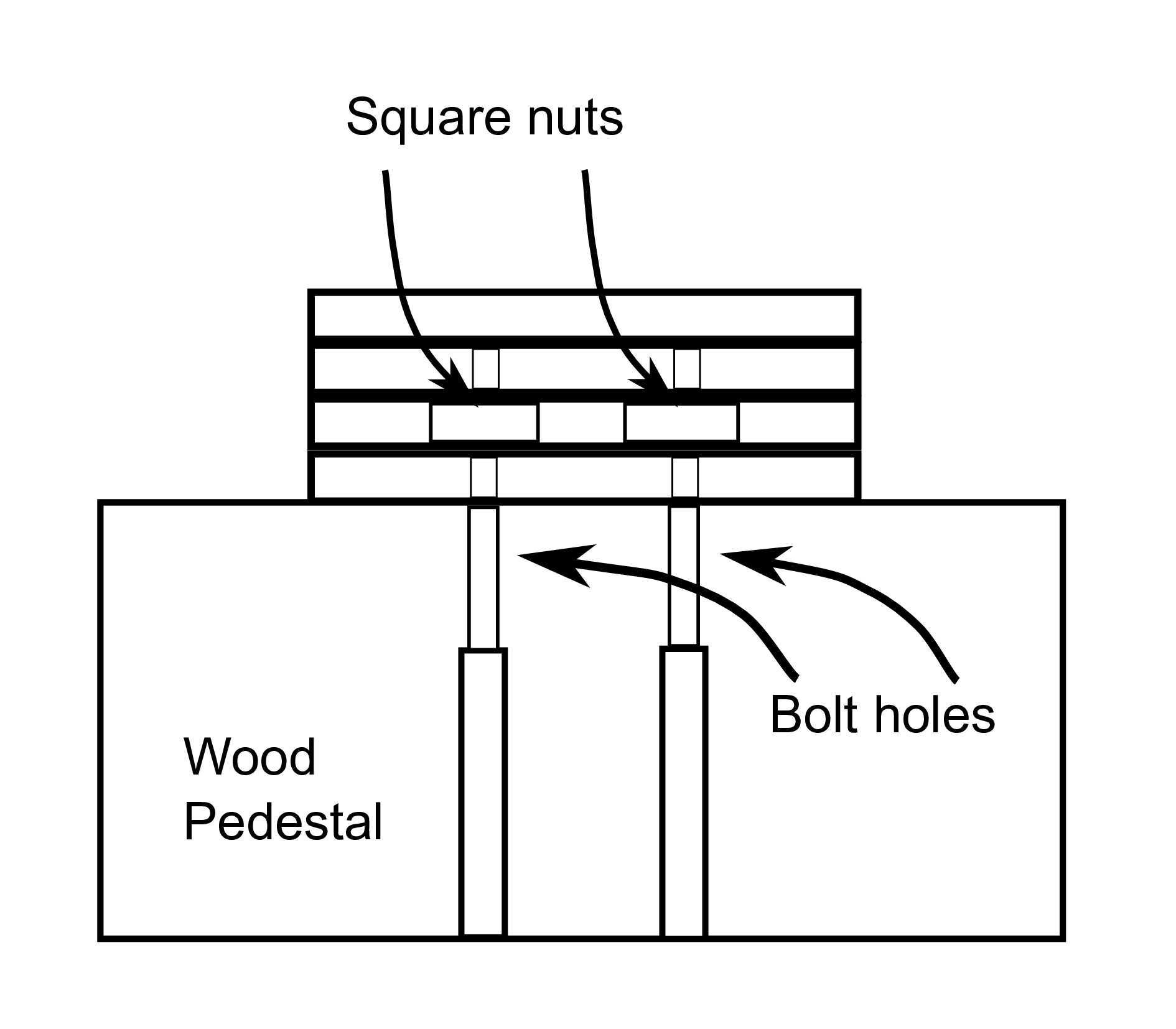
I designed a set of 4 elliptical pieces that would be stacked to make up the base (Fig. 8). I cut these on the laser from 1/8 inch acrylic. I had the laser cut 2 square holes for a pair of old, 4-sided nuts in one piece. This layer was sandwiched between 2 with holes cut just larger than the machine screw that matched placement of the nuts. When all the layers were glued together, the nuts were captured, but allowed to ‘float’ within the opening, to allow the screws to self-align. The reason for the holes in the layer above the nuts was to allow the screws to protrude through the nut layer without putting strain on the joint with the top layer. The top layer was solid, and the figure would be attached to this (Fig. 9).
Once the base was assembled, the sides were sanded and gaps filled. Finally, it was painted flat black and the figure was attached (Fig. 10).
Engraved Plates
The only issue still to be addressed was the question of getting engraved plates for the trophy title and the annual winner. I determined the dimensions that would be needed and went online to find a trophy shop to order them. One search result was a company named Main Trophy Supply, and when I looked at the website, they sold laser-etchable coated metal stock. They were only about 5 miles from me, and I thought I might as well visit them to actually see their stock, rather than order from pictures online.
I stopped by one afternoon, and explained (to the owner, as it happened) what I was doing and what I would need. He very generously offered to just give me what would be needed, no charge! He also gave me the cook’s tour of their warehouse. Tthey apply the etchable coatings to rolls of brass and aluminum from which they cut standard size sheets. All made in America.
They also sell small table-top shears and punches to work with the sheets of materials. This kind gentleman cut 3 sheets for the title plate, and a couple of dozen pieces for the winner plates. And he punched screw holes and gave me a handful of small wood screws to attach them! I’m now lobbying our library to purchase the tools to work with the sheet stock, to allow others to use the laser cutter for similar projects.
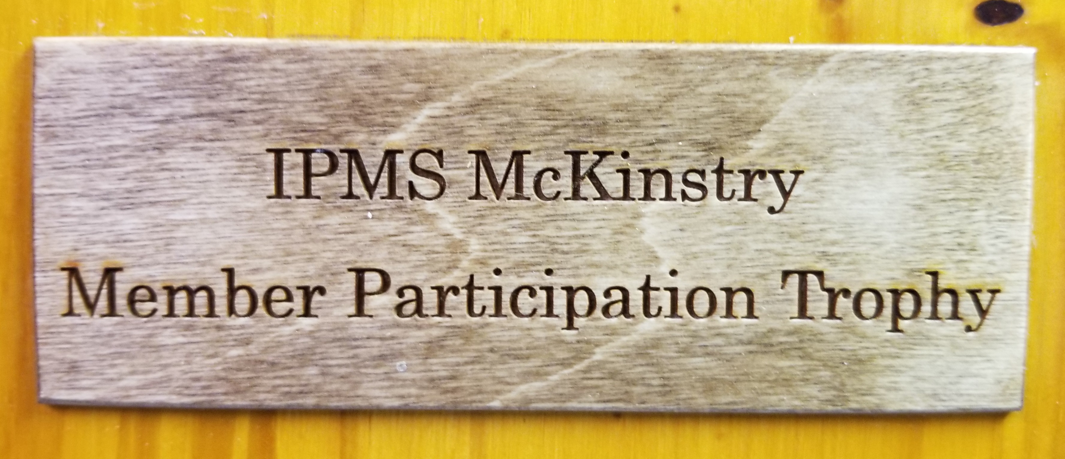
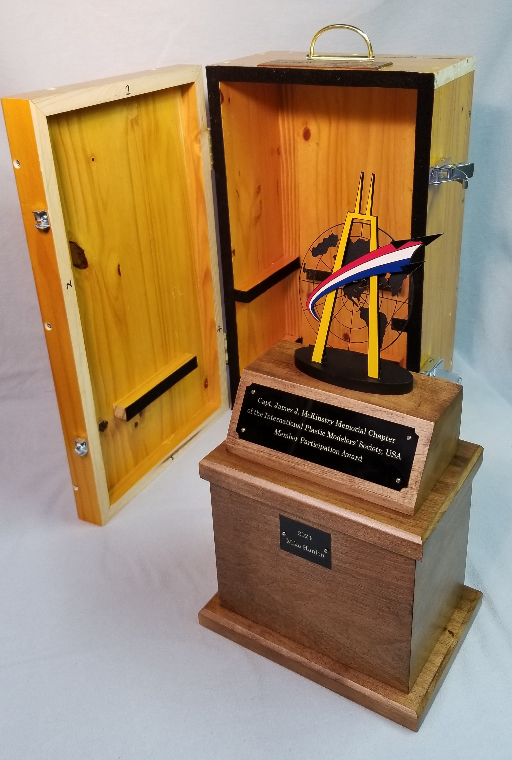
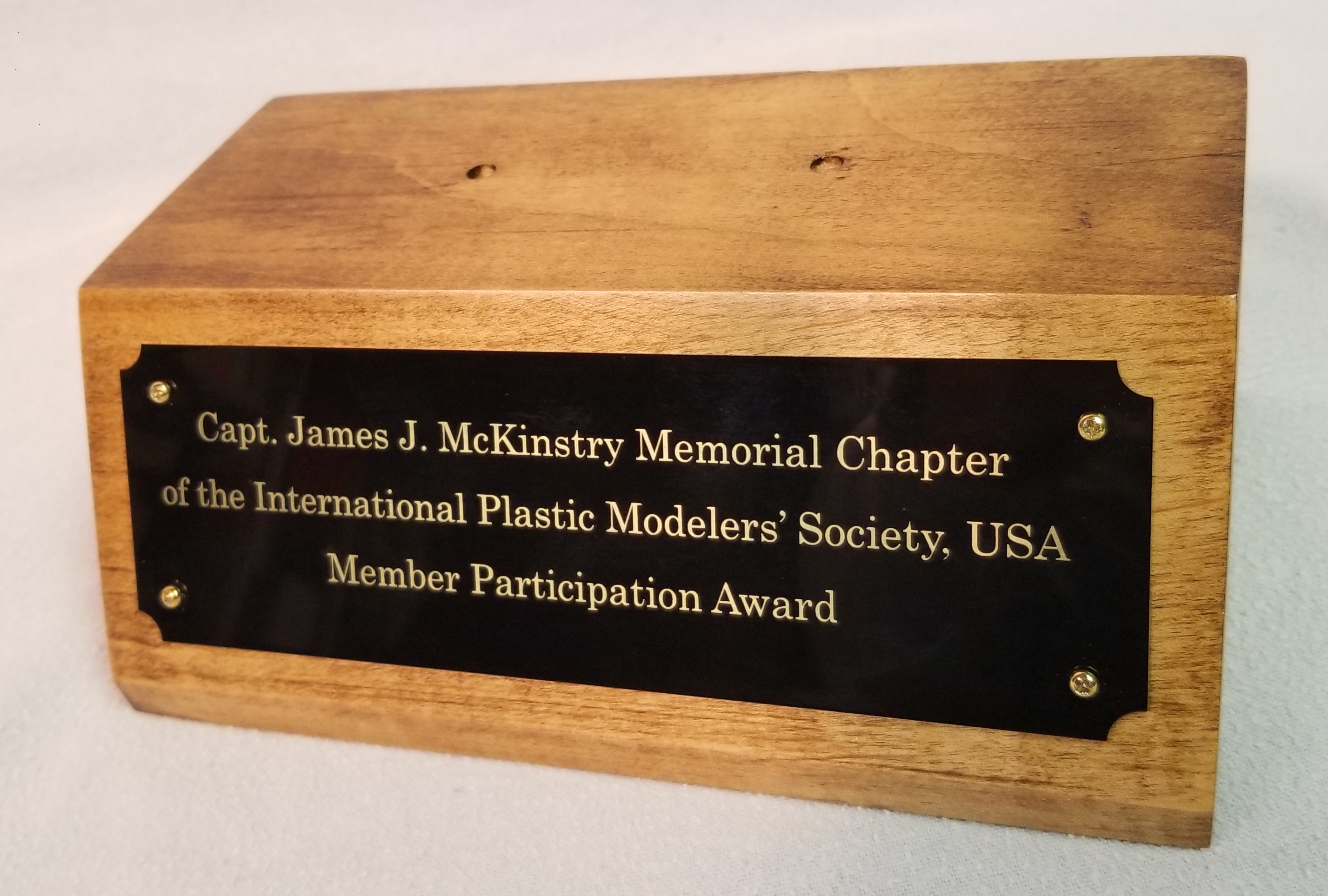
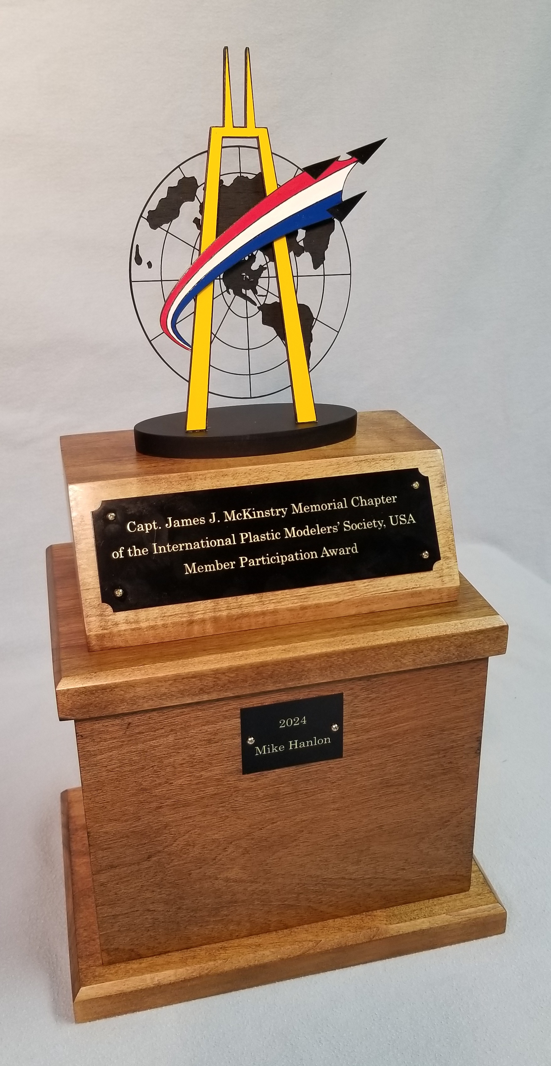
Since the design for the text needed to be prepared for the laser as a PDF, almost any word processing software could be used to create these designs, but I used Inkscape for this, as well. I used the Epilog laser to etch these plates because the Dremel had a calibration problem when I needed to do this engraving. The finished title plate, mounted on the pedestal, can be seen in Fig. 11, and the finished trophy in Fig. 12.
Travel Case
One final issue presented itself to me when I took the first prototype of the trophy to our annual holiday party in December. The figure was temporarily attached to the trophy with double-sided tape. It was a particularly windy evening, and the figure blew off before I could get out of the parking lot.
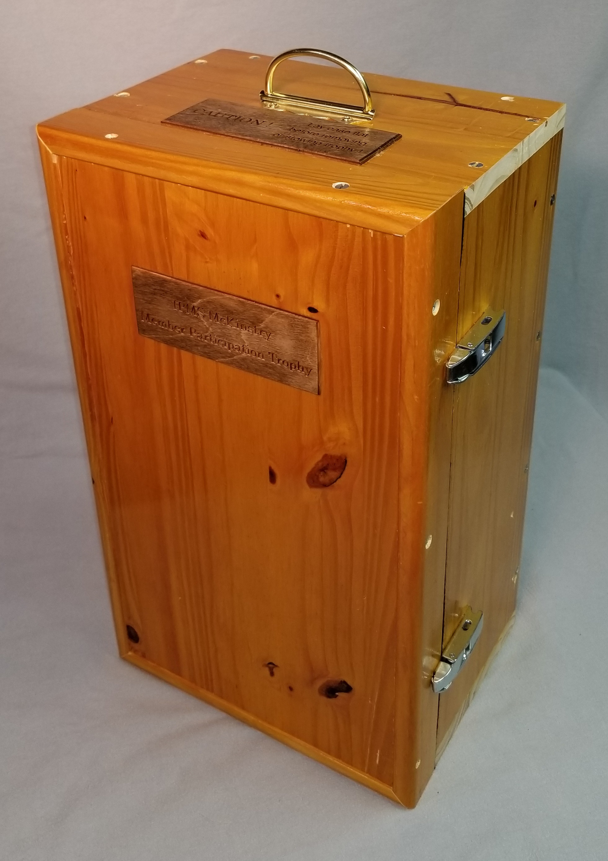
I concluded that the travelling trophy would require a travel case. I had a pine countertop that I’d removed from the basement, so I cut pieces from it to make the travel case. A couple of hinges and some other hardware and it was ready to go.
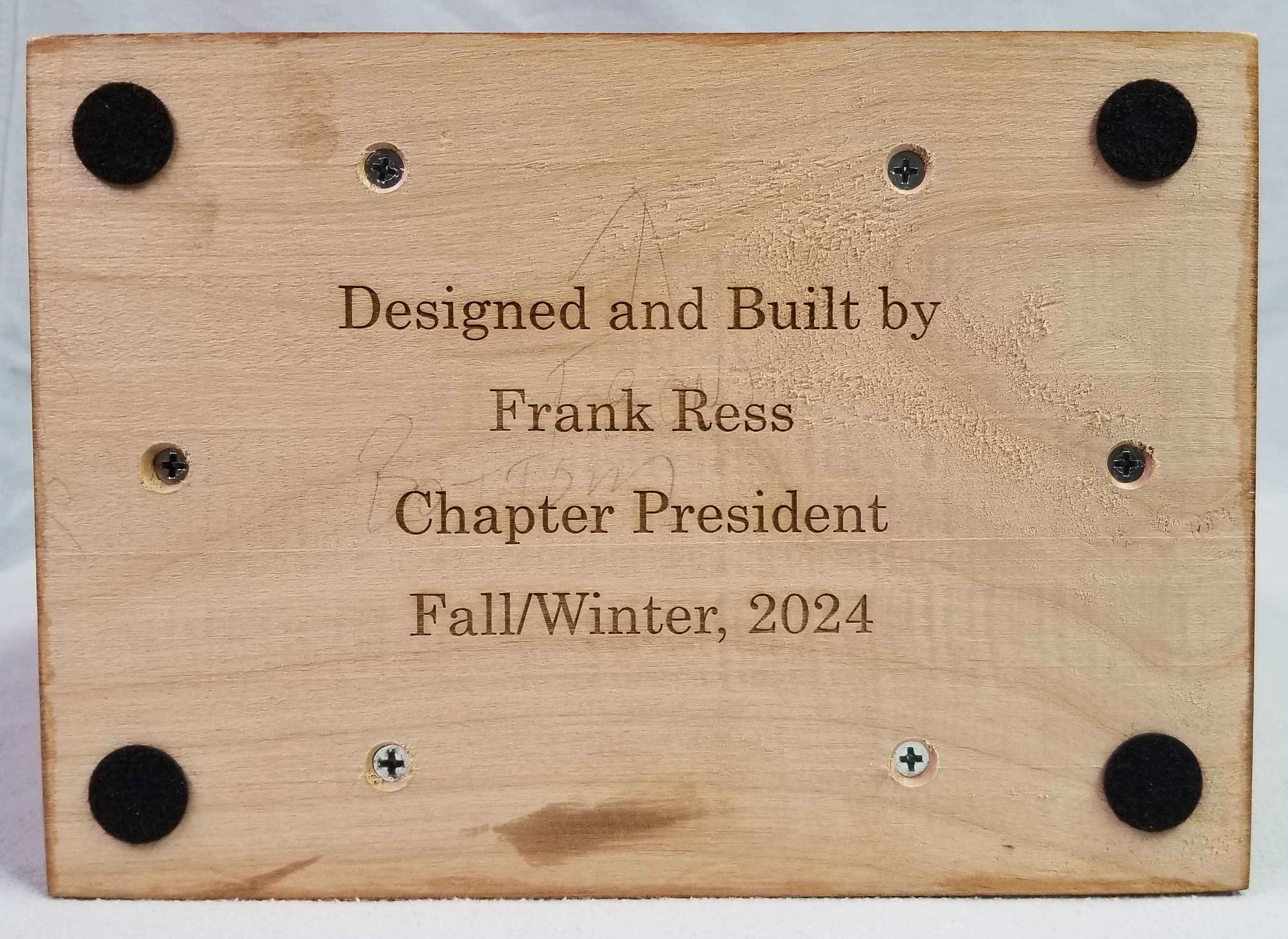
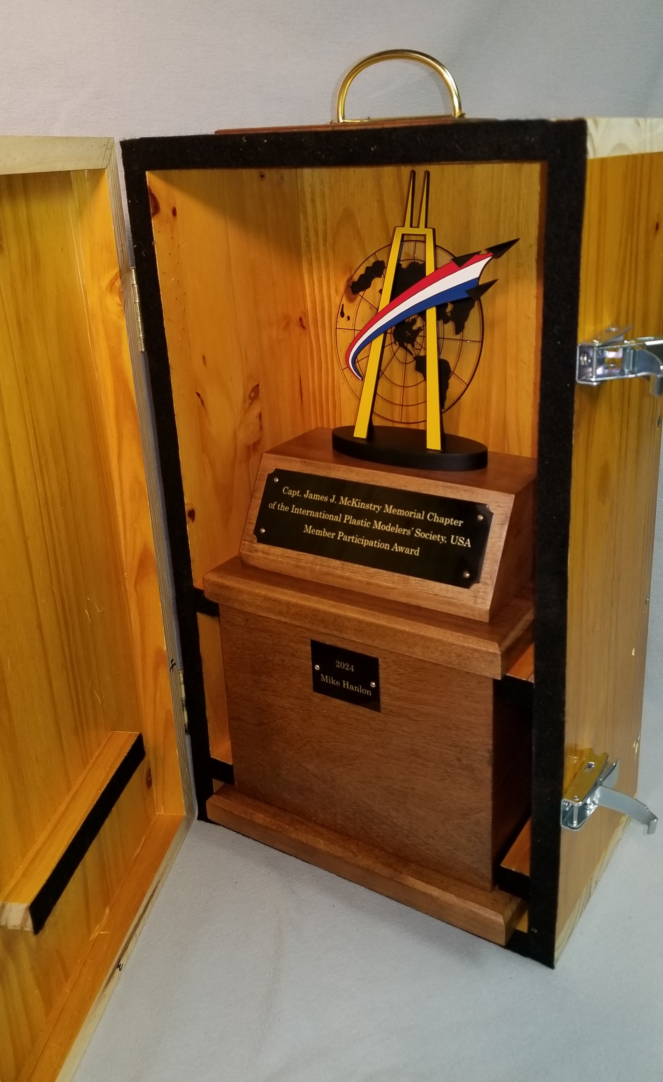
I used some 1/8” plywood to etch label and instruction plates for the case, and to etch a vanity signature to the bottom of the trophy (Figs. 13 and 14). The finished trophy and its case can be seen in Figs. 15-17.